
Views: 0 Author: Site Editor Publish Time: 2026-06-15 Origin: Site


Hydraulic hose wear is an inevitable reality in heavy machinery operation. You cannot stop parts from aging over time. However, catastrophic failure—like an unexpected bursting event—introduces unacceptable operational, financial, and safety risks. You simply cannot ignore the sudden danger of a blown high-pressure line.
Basic maintenance routines help, but they have distinct limits in real-world scenarios. We must shift our focus from routine checks to proactive risk mitigation. Engineers need advanced solutions specifically addressing load-holding safety and the prevention of uncontrolled fluid release.
This article introduces the evaluation of burst valves as a compliance-driven, fail-safe mechanism. You will discover how these specific devices protect high-stakes industrial and mobile machinery. We will guide you through common failure causes and operational impacts. Expect clear, practical guidelines on selecting and implementing the right valve successfully to protect your assets.
Hose bursts are primarily driven by pressure spikes, improper routing, and localized abrasion, leading to sudden loss of system integrity.
A hose burst valve acts as a velocity fuse, instantly isolating flow during a rupture to prevent uncontrolled load descent and minimize fluid loss.
Selecting the right valve requires precise matching of normal flow rates (GPM/LPM) to prevent false tripping while maintaining operational efficiency.
When a hydraulic line blows, the consequences stretch far beyond replacing the ruined component. You face cascading business disruptions immediately. Ruptured lines spray gallons of hot, pressurized oil across the job site. Environmental cleanup crews charge a massive premium for emergency hazardous material responses. Furthermore, local authorities and the EPA routinely issue steep fines for these hazardous spills. The impact on production is equally severe. Extended unplanned downtime halts entire production lines or construction schedules. You lose operational capacity and revenue every single minute the machine sits idle waiting for repairs.
Next, consider the severe safety and compliance realities involved. Uncontrolled cylinder descent poses massive risks to personnel and infrastructure. Imagine an excavator dropping a heavy concrete pipe simply because a rubber line snapped. Scissor lift platforms can collapse rapidly, endangering human lives instantly. OSHA enforces strict safety protocols regarding suspended loads and hydraulic failures. Regulatory bodies do not accept ignorance as an excuse. Industry standards clearly dictate heavy liability for preventable workplace accidents. Proactive safety measures remain non-negotiable for modern fleet managers and design engineers.
We must also acknowledge the inherent limits of preventive maintenance. Regular inspection schedules build a trustworthy baseline for fleet health. Mechanics catch many visible issues early, like weeping fittings or cracked outer covers. However, visual checks cannot predict every single failure scenario. They frequently miss hidden structural fatigue deep inside the internal wire braid. A sudden dynamic pressure spike bypasses routine maintenance checks entirely. Even the most rigorous maintenance programs cannot guarantee absolute immunity from sudden, violent ruptures. You need a dedicated physical barrier to stop the fallout.
Operators and design engineers must understand exactly what causes catastrophic failures. Several primary catalysts trigger these dangerous events in industrial environments. Recognizing these threats helps you build better system defenses.
Dynamic Pressure Overload (Spikes): Sudden load shifts generate massive hydraulic shock within the circuit. This intense force spike easily exceeds the maximum working pressure rating of the hose. The internal structure tears apart instantly under the strain. A catastrophic rupture follows immediately, venting fluid violently.
Routing and Bend Radius Violations: Machine designs often cram hydraulic components into impossibly tight spaces. Forcing a line past its specified minimum bend radius causes severe mechanical stress. This tension stretches the outer wire reinforcement dangerously thin. The component's overall burst tolerance drops dramatically as a result of poor installation geometry.
Mechanical Chafing and Abrasion: Heavy equipment vibrates constantly during normal operation. Continuous friction against metal frames rubs away the protective outer rubber cover. The exposed metal wire braid inevitably rusts when exposed to moisture. Structural degradation accelerates rapidly once the internal wire matrix loses its protective jacket.
Incompatible Fluids and Temperature Extremes: Thermal limits protect the internal elastomer materials from chemical breakdown. Operating outside specified thermal ranges literally cooks the inner tube over time. Chemical incompatibility from incorrect hydraulic fluids also degrades the core material. The compromised rubber eventually yields under standard operating pressures.
A dedicated fail-safe changes the entire safety equation for heavy equipment. You need a mechanism designed specifically for sudden, catastrophic ruptures. This is exactly where a hose burst valve becomes essential. It acts as an automatic guardian for your fluid circuits.
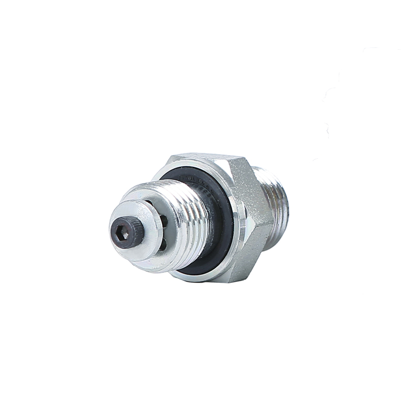
Engineers often call this clever device a velocity fuse. The technical reality of its operation is highly effective yet elegantly simple. Under normal operating conditions, fluid flows freely through the internal passages of the cartridge. The internal poppet remains open against spring tension. However, when a catastrophic rupture occurs, fluid velocity spikes dramatically. The flow speed instantly exceeds a precisely pre-set threshold. This sudden rush of fluid overcomes the internal spring and snaps the valve shut. It isolates the flow completely in milliseconds.
This instant closure guarantees reliable load locking. Trapping the fluid securely inside the cylinder freezes the actuator firmly in place. Uncontrolled load drops become physically impossible. Gravity cannot force the cylinder down when the supporting fluid has nowhere to escape. This failsafe operation directly protects workers, expensive materials, and the machine itself from catastrophic damage.
Location matters enormously during the implementation process. You must install these safety components directly into the actuator or cylinder port. Threading them anywhere downstream totally defeats their intended purpose. If a line breaks somewhere between the cylinder and the safety mechanism, the fluid escapes anyway. The load will fall despite having the valve in the circuit. Direct port installation is a strict, non-negotiable rule for effective load holding.
Selecting the right component requires careful evaluation and precise calculations. You must match the device accurately to your specific machinery demands.
Flow Rate (GPM/LPM) Calibration represents your most critical buying decision. You absolutely cannot guess the required threshold. The closing flow setting must be slightly higher than your system's maximum normal return flow. Engineers typically aim for a 20-30% buffer margin. If you set it too close to normal operating speeds, it trips unnecessarily. If you set it too high, it might not activate during a partial rupture.
Consider the following calibration examples for standard industrial setups:
Normal System Flow (LPM) | Recommended Safety Buffer | Calculated Trip Threshold (LPM) |
|---|---|---|
50 | 25% | 62.5 |
80 | 20% | 96.0 |
120 | 30% | 156.0 |
200 | 25% | 250.0 |
Next, you must choose between adjustable and fixed cartridges. Each style serves a highly distinct operational purpose. Proper selection impacts long-term maintenance needs. Here is a brief chart comparing their primary attributes:
Feature Category | Adjustable Cartridges | Fixed Cartridges |
|---|---|---|
Flexibility | High; highly suitable for variable load applications. | Low; permanently preset at the factory. |
Tamper Resistance | Vulnerable to unauthorized field tweaks by operators. | Highly secure, ensuring tamper-proof compliance. |
Best Application | Prototyping, testing, and highly varying operations. | Standardized OEM production runs and fleet setups. |
Thread and fitting compatibility also demands extremely close attention. Match your port types accurately before ordering. Common global standards include BSP, NPT, and various SAE configurations. Using multiple adapters introduces unnecessary leak points into a high-pressure system. Always buy the precise thread type your specific cylinder requires naturally.
Finally, evaluate necessary regulatory standards. Heavy machinery often faces incredibly strict compliance rules globally. ISO 8643 formally governs earth-moving machinery standards regarding load control. European markets explicitly demand CE certifications for mobile equipment. Proper sourcing helps your machinery easily clear these stringent regulatory hurdles.
Theory often differs from field implementation. You will face specific operational realities when installing these safeguards. Understanding potential risks prevents major engineering headaches later.
The risk of false tripping frustrates equipment operators frequently. A rapid, entirely normal machine cycle can suddenly trigger closure. The machine jerks to a violent halt unexpectedly. Operators lose valuable time trying to diagnose and fix it. The solution requires precise flow calculation upfront during the design phase. You must also implement proper system dampening techniques. Smoothing out erratic flow spikes prevents premature locking. A properly calibrated hose burst valve in hydraulic systems works silently without ever interrupting normal tasks.
System pressure drop, commonly known as Delta P, represents another reality. Adding any component into a fluid circuit introduces a slight restriction. Pressurized fluid must push past internal poppets and springs. You must maintain transparency regarding overall system efficiency calculations. Account for this minor energy loss during the initial design phase. Heavy equipment usually overcomes this resistance easily, but highly precise hydraulic tools might require minor pressure adjustments.
Reset procedures demand specific, safe maintenance steps. A locked actuator stays rigidly locked until you intervene safely. You must never try to force it open manually under pressure. Follow these realistic steps to reset the circuit after a burst event occurs:
Shut down the primary hydraulic pump instantly and secure the immediate working area.
Safely support the suspended load using approved mechanical blocks or auxiliary cranes.
Remove the ruptured hose completely and inspect adjacent fittings for stress damage.
Install the replacement hose and ensure all thread connections are torqued correctly.
Gradually bleed hydraulic fluid into the new line to equalize pressure on both sides of the cartridge.
Once pressure equalizes fully, the internal spring automatically unseats the safety poppet.
Run the actuator slowly through a complete test cycle before resuming normal field operations.
To summarize, these fail-safe devices act as a highly targeted insurance policy. They specifically protect your machinery and personnel against the catastrophic fallout of sudden failure. However, they are never a valid replacement for good routing practices. Proactive, scheduled maintenance remains an essential pillar of equipment management. You must combine strong physical safeguards with intelligent inspection routines.
Engineers and procurement teams must take clear action now. Start by conducting a thorough audit of your critical load-holding cylinders first. Identify which actuators pose the greatest safety risk if a line fails. Calculate the maximum return flows accurately for each identified circuit. Finally, consult directly with a qualified hydraulics specialist. They will help you confidently source appropriately rated components for your exact field applications.
A: No, it cannot prevent minor weeping or slow leaks. This device specifically prevents massive fluid loss during a full, catastrophic rupture. It functions as an emergency shut-off triggered by sudden high velocity. Small leaks do not generate enough fluid speed to activate the internal mechanism. You must still rely on regular inspections to catch slow leaks.
A: You must equalize the pressure on both sides of the cartridge. First, mechanically support the suspended load safely. Replace the blown line with a new, properly rated component. Slowly introduce fluid pressure back into the repaired circuit. Once the pressure balances, the internal spring automatically pushes the poppet open, restoring normal system flow.
A: No, you do not need them everywhere. You should prioritize load-lifting cylinders and safety-critical vertical actuators. Applications like excavator booms, scissor lifts, and crane hoists require them. Standard horizontal push or pull applications generally do not pose the same severe safety risks during a sudden fluid loss.


