


Hose failures are rarely spontaneous events. Whether they occur in high-pressure water applications or heavy-duty machinery, they result from predictable mechanical, thermal, or operational stress. Equipment operators often overlook early warning signs until a sudden rupture violently disrupts operations. A burst line might seem like a minor inconvenience in residential plumbing setups, but it rapidly escalates into a critical safety hazard in industrial environments. Sudden fluid loss endangers machine operators, damages expensive equipment, and halts production schedules entirely. Relying solely on visual inspections leaves fluid systems vulnerable to unseen internal fatigue. Preventing these catastrophic drops in pressure requires more than just rigorous daily maintenance routines. We must integrate automatic fail-safes into our fluid networks to guarantee operational security. In this comprehensive guide, you will discover the primary root causes of line ruptures. You will also learn exactly how to implement robust protective solutions to secure your heavy machinery and fluid infrastructure against unpredictable blowouts.
Hoses typically burst due to pressure spikes, material fatigue, abrasive wear, or thermal expansion (freezing).
In industrial and high-pressure environments, a burst hose introduces severe safety risks, environmental compliance issues, and costly unplanned downtime.
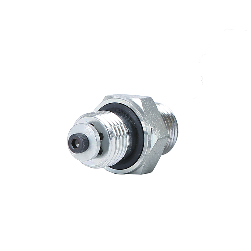
A hose burst valve acts as an automatic, instantaneous fail-safe by locking out flow when a sudden drop in pressure is detected.
Selecting the right safety valve requires evaluating flow rates, system pressure, and understanding the operational realities of pressure drops.
Understanding why fluid lines rupture helps us engineer better preventive strategies. Failures stem from a combination of environmental factors and extreme operational demands. Below are the primary culprits behind catastrophic line blowouts.
Dynamic Pressure Spikes (Water Hammer): Sudden valve closures stop fluid flow instantly. The kinetic energy of the moving fluid cannot simply vanish. It converts directly into violent pressure shockwaves. We commonly call this phenomenon water hammer. These internal shockwaves easily exceed the designed burst strength of the internal tubing. The material balloons outward and eventually rips open.
Material Degradation and Fatigue: Industrial lines degrade silently over time. Prolonged UV exposure breaks down synthetic rubber compounds. Harsh industrial chemicals erode internal linings. Continuous flexing weakens the structural wire braids. The overall structural integrity degrades steadily. Routine pressure cycles eventually push the fatigued material past its breaking point.
External Abrasions and Routing Errors: Poor installation accounts for countless premature failures. Technicians sometimes force lines into tight bend radii. This unnatural bending stretches the outer protective layers dangerously thin. Lines often rub against vibrating chassis components or moving machinery parts. Constant friction strips away the tough outer jacket. The internal reinforcement layers become exposed and quickly rust or snap.
Thermal Extremes: Ambient temperatures drastically alter material strength. Freezing temperatures cause internal fluids to freeze and expand. Water expands by roughly nine percent when frozen. This immense outward force easily splits metal fittings and rubber hoses alike. Conversely, extreme operational heat softens polymer compounds. The softened material loses its tensile strength and gives way under normal operating pressures.
Ignoring line vulnerabilities carries heavy consequences. A sudden rupture triggers a cascade of negative business impacts. Organizations face compounding financial and operational penalties when fail-safes are absent.
Operational Downtime: System paralysis strikes immediately following a blowout. You must halt entire production lines or construction vehicles instantly. Teams wait hours for hazardous fluid cleanup. Sourcing and installing replacement components burns through valuable operational schedules. The financial cost of idle machinery and stalled labor accumulates rapidly.
Safety and Compliance Risks: High-pressure blowouts present terrifying physical dangers. Fluid injection injuries occur when escaping hydraulic fluid pierces human skin. This highly toxic fluid enters the bloodstream and requires emergency surgical intervention. Severed lines become unpredictable whipping hazards, striking nearby personnel with lethal force. Lifting equipment suffers uncontrolled load drops if holding lines fail. These incidents trigger immediate regulatory audits and severe workplace safety violations.
Environmental and Cleanup Costs: Unprotected systems pose significant ecological threats. Hydraulic fluid spills frequently contaminate local soil on construction sites. Chemical leaks can enter municipal drainage systems. Regulatory bodies issue massive financial penalties for these environmental breaches. Professional hazmat cleanup efforts drain annual operating budgets. You face serious reputational damage alongside the direct financial penalties.
Engineering a truly resilient fluid circuit requires immediate, automatic protection. A hose burst valve serves as your primary line of defense. Industry professionals often call these devices velocity fuses. They deliver instantaneous security during catastrophic events.
The valve mechanism relies on elegant fluid dynamics. It stays completely open during normal, controlled flow operations. An internal poppet monitors fluid velocity constantly. When a downstream line ruptures, resistance drops to zero. The fluid velocity spikes dramatically. The valve detects this sudden velocity surge instantly. The internal poppet overcomes its spring tension and snaps shut. This action locks out flow entirely and seals the pressurized circuit.
You must understand the distinct operational goals of these components. They serve two critical but slightly different primary functions in heavy equipment.
Function Category | Primary Objective | Common Application |
|---|---|---|
Load Holding | Prevents a hydraulic cylinder from collapsing under heavy weight during a line failure. | Excavator booms, scissor lifts, crane outriggers. |
Line Protection | Stops massive fluid leakage from a severed delivery line to protect the reservoir. | Industrial fluid transfer, chemical dosing lines. |
These fail-safes thrive in demanding environments. They utilize purely mechanical fluid dynamics. They contain no fragile external electronic sensors. They require no electrical wiring harnesses. This mechanical simplicity guarantees extreme reliability. Mud, severe vibration, and complete water submersion do not disrupt their function. They remain vigilant and ready to activate at a moment's notice.
Selecting the correct safety device requires careful engineering analysis. A mismatched component will restrict performance or fail to activate entirely. You must evaluate several critical design parameters.
Flow rate calibration forms the foundation of proper specification. You must establish a precise baseline requirement. Calibrate the valve's closing flow slightly above your system's maximum normal operational flow. If you set the threshold too low, normal machine operations will trigger a lockout. We call this frustrating phenomenon nuisance tripping. If you set the threshold too high, a partial line rupture might not generate enough velocity to close the poppet.
Engineers must choose between two distinct cartridge designs.
Fixed Cartridges: Manufacturers preset these at the factory. They are completely tamper-proof. They deliver highly reliable, repeatable performance. Standardized OEM equipment fleets benefit greatly from fixed configurations. Operators cannot accidentally alter the safety settings in the field.
Adjustable Cartridges: These offer crucial flexibility for custom machinery. Technicians can dial in specific closing flow rates during commissioning. They work perfectly for retrofit projects. Variable load systems require this adaptability to function smoothly across different operational modes.
Installation location dictates the effectiveness of the protection. You must mount the hose burst valve in hydraulic systems as close to the actuator as physically possible. Ideally, thread the valve housing directly into the cylinder port. This placement minimizes the length of unprotected fluid line. Any hose located between the safety device and the cylinder remains completely unprotected.
Housing materials must endure severe external conditions. Zinc-plated steel provides excellent durability for standard industrial applications. It resists basic environmental corrosion effectively. Stainless steel becomes mandatory for offshore marine environments or harsh chemical processing plants. You must always verify the maximum working pressure rating. The valve body must safely handle your circuit's absolute peak pressure spikes.
Best Practice: Always base your sizing decisions on measured flow metrics (gallons or liters per minute). Do not simply match the physical port thread size and assume the flow rating is correct.
Common Mistake: Ignoring fluid viscosity changes. Cold hydraulic oil is thicker. It generates higher pressure drops at lower velocities. This frequently causes unexpected nuisance tripping during winter mornings.
Integrating new safety hardware introduces new operational dynamics. Engineering teams must anticipate and mitigate these challenges during the design phase. Transparency regarding these realities ensures successful deployment.
Introducing any inline component creates a slight restriction. Fluid pushes past the internal poppet and spring. This action generates a measurable pressure drop. It also generates minor internal heat. You cannot avoid this physical reality. Design engineers must size the overall pumping system to accommodate this slight efficiency loss. Undersized systems will suffer sluggish actuator response times.
Installation orientation is an absolute critical factor. These units are strictly directional. They monitor and protect flow moving in one specific direction. They only lock out fluid moving *out* of the protected cylinder or actuator. Reverse-installation errors happen frequently in the field. A backwards valve provides zero burst protection. It simply allows free flow out and restricts flow going in. Installers must strictly follow the directional arrows stamped on the outer housing.
Particulate contamination threatens the internal moving parts. Tiny metal shavings or dirt particles can lodge inside the housing. This debris jams the poppet mechanism against the inner walls. A jammed valve cannot snap shut during an emergency blowout. You must maintain rigorous upstream filtration standards. Follow strict ISO fluid cleanliness codes to ensure the poppet glides smoothly during a crisis.
Proving the device actually works presents a unique maintenance challenge. You cannot simply slice a pressurized line to test the fail-safe. Testing requires safely simulating a sudden burst event. Technicians utilize specific commissioning protocols. They use controlled bleed valves to dump flow rapidly into a secure secondary reservoir. This safely simulates the required velocity spike. Proper documentation of these tests ensures ongoing compliance.
Implementation Pitfall | Real-World Consequence | Corrective Action |
|---|---|---|
Backwards Installation | Zero protection during a line rupture; possible actuator cavitation. | Verify stamped flow arrows before final torqueing. |
Undersized Closing Flow | Machine unexpectedly locks up during rapid, normal movements. | Recalibrate adjustable valves or install a higher-flow fixed cartridge. |
Poor Fluid Filtration | Internal poppet seizes; fail-safe fails to activate when needed. | Install high-efficiency return line filters and monitor fluid cleanliness. |
Routine visual inspections and disciplined maintenance schedules significantly extend hose life. However, blowouts remain a statistical probability in any high-stress environment. Mechanical fatigue, thermal extremes, and unpredictable pressure spikes inevitably take their toll. You cannot eliminate the risk of a rupture entirely. You can only control how your machinery responds when that rupture happens.
Facility managers and mechanical engineers must take proactive steps. Audit your critical lifting infrastructure, load-holding cylinders, and high-pressure fluid networks immediately. Identify unprotected circuits where a sudden failure would cause catastrophic injury or severe financial loss. Upgrading these vulnerable points ensures absolute fail-safe compliance.
Do not wait for a blowout to force an expensive retrofit. Consult a specialized technical sizing guide to begin your evaluation. Utilize an accurate flow-rate calculation tool to determine your exact velocity thresholds. Reach out for professional engineering consultation today to specify the perfectly calibrated valve for your specific machine architecture.
A: You should never splice or patch a high-pressure burst line. Temporary repairs compromise structural integrity and violate basic safety standards. A compromised outer jacket or inner braid cannot handle restored pressure spikes safely. You must completely remove the damaged section and install a brand-new, factory-crimped assembly to guarantee operational safety.
A: No, they operate differently. A standard check valve prevents absolutely any reverse fluid flow under all conditions. In contrast, a burst valve allows controlled, normal reverse flow to pass through it freely. It only seals the circuit when that reverse flow exceeds a specific, dangerous velocity limit.
A: Specific industries mandate their use. Organizations like OSHA and ISO enforce strict load-holding and fall-protection standards. Heavy equipment like scissor lifts, excavators, and material handling cranes must utilize these fail-safes. They prevent uncontrolled load drops and protect operators from crushing hazards if main pressure lines fail.
A: We call this nuisance tripping. It usually stems from improperly calibrated flow rates set too close to normal operating velocities. Thick, cold hydraulic fluid also creates unexpectedly high pressure drops that trick the poppet. Finally, jerking the manual control levers too aggressively can create temporary velocity spikes that trigger premature closure.


