Please Choose Your Language


The SAE straight 4-bolt flange with EO 24° cone end is a hydraulic connection component used to connect hydraulic tubes to compatible flange ports. The four-bolt mounting arrangement provides a secure mechanical connection, while the EO 24° cone end is designed for connection with compatible tube fittings.
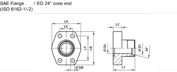
The product is available in 3000 PSI and 6000 PSI series, with different dimensions, bolt arrangements, and pressure ratings depending on the selected size and configuration. The dimensional specifications include flange dimensions, tube connection dimensions, bolt spacing, screw specifications, and reference pressure ratings.
For correct selection, the nominal flange size, tube connection size, pressure requirements, and mating port specifications should be checked against the product dimensional table.
SAE straight 4-bolt flange connection design
EO 24° cone tube connection
Available in 3000 PSI and 6000 PSI series
Multiple nominal flange sizes and tube connection options
Designed for hydraulic tube and flange-port connections
Dimensional specifications provided for flange mounting and tube connections
Suitable for hydraulic machinery and industrial fluid systems
Selection based on size, connection type, and pressure requirements
| 3000 PSI Series | |||||||||||||||
| Nom. flange size (in.) | D12) a | D3 | L1 | L2 | LA | LB | LX | LY | DB | Screw | Weight (kg/piece) | PN (bar)1) | |||
| SAE (in.) | ISO (DN) | (metric.) | (unc.) | CF | SS | ||||||||||
| 1/2 | 13 | 12S | 8 | 47 | 16 | 42 | 57 | 17 1/2 | 38 1/9 | 9 | M 08×30 | 5/16×1 1/4 | 1/4 | 348 | 348 |
| 1/2 | 13 | 15L | 11 | 47 | 16 | 42 | 57 | 17 1/2 | 38 1/9 | 9 | M 08×30 | 5/16×1 1/4 | 2/7 | 348 | 315 |
| 1/2 | 13 | 16S | 12 | 47 | 16 | 42 | 57 | 17 1/2 | 38 1/9 | 9 | M 08×30 | 5/16×1 1/4 | 1/3 | 348 | 315 |
| 3/4 | 19 | 16S | 12 | 52 | 18 | 50 | 66 | 22 2/7 | 47 3/5 | 11 | M 10×35 | 3/8×1 1/2 | 1/3 | 348 | 348 |
| 3/4 | 19 | 20S | 16 | 52 | 18 | 50 | 66 | 22 2/7 | 47 3/5 | 11 | M 10×35 | 3/8×1 1/2 | 3/8 | 348 | 348 |
| 3/4 | 19 | 22L | 18 | 52 | 18 | 50 | 66 | 22 2/7 | 47 3/5 | 11 | M 10×35 | 3/8×1 1/2 | 3/8 | 250 | 160 |
| 1 | 25 | 20S | 16 | 55 | 18 | 53 | 71 | 26 1/5 | 52 2/5 | 11 | M 10×35 | 3/8×1 1/2 | 4/9 | 348 | 348 |
| 1 | 25 | 25S | 20 | 55 | 18 | 53 | 71 | 26 1/5 | 52 2/5 | 11 | M 10×35 | 3/8×1 1/2 | 4/9 | 348 | 348 |
| 1 | 25 | 28L | 23 | 55 | 18 | 53 | 71 | 26 1/5 | 52 2/5 | 11 | M 10×35 | 3/8×1 1/2 | 1/2 | 250 | 160 |
| 1 1/4 | 32 | 25S | 20 | 60 | 21 | 69 | 80 | 30 1/5 | 58 5/7 | 11 1/2 | M 10×40 | 7/16×1 1/2 | 2/3 | 278 | 278 |
| 1 1/4 | 32 | 30S | 25 | 60 | 21 | 69 | 80 | 30 1/5 | 58 5/7 | 11 1/2 | M 10×40 | 7/16×1 1/2 | 5/7 | 278 | 278 |
| 1 1/4 | 32 | 30S | 25 | 60 | 21 | 69 | 80 | 30 1/5 | 58 5/7 | 11 1/2 | M 10×40 | 7/16×1 1/2 | 5/7 | 278 | 278 |
| 1 1/2 | 38 | 35L | 30 | 70 | 25 | 77 | 94 | 35 5/7 | 69 8/9 | 13 1/2 | M 12×45 | 1/2×1 3/4 | 1 | 210 | 210 |
| 1 1/2 | 38 | 38S | 32 | 70 | 25 | 77 | 94 | 35 5/7 | 69 8/9 | 13 1/2 | M 12×45 | 1/2×1 3/4 | 1 | 210 | 210 |
| 1 1/2 | 38 | 42L | 36 | 70 | 25 | 77 | 94 | 35 5/7 | 69 8/9 | 13 1/2 | M 12×45 | 1/2×1 3/4 | 1 | 210 | 210 |
| 2 | 51 | 38S | 32 | 74 | 25 | 90 | 103 | 42.9 | 77.8 | 13.5 | M 12×45 | 1/2×1 3/4 | 1.4 | 210 | 210 |
| 2 | 51 | 42L | 36 | 74 | 25 | 90 | 103 | 42.9 | 77.8 | 13.5 | M 12×45 | 1/2×1 3/4 | 1.35 | 210 | 210 |
| 6000 PSI Series | |||||||||||||||
| 1/2 | 13 | 12S | 8 | 47 | 16 | 47 | 57 | 18 2/7 | 40 1/2 | 9 | M 08×30 | 5/16×1 1/4 | 2/7 | 420 | 420 |
| 1/2 | 13 | 14S | 10 | 47 | 16 | 47 | 57 | 18 2/7 | 40 1/2 | 9 | M 08×30 | 5/16×1 1/4 | 1/3 | 420 | 420 |
| 1/2 | 13 | 16S | 12 | 47 | 16 | 47 | 57 | 18 2/7 | 40 1/2 | 9 | M 08×30 | 5/16×1 1/4 | 1/3 | 420 | 420 |
| 3/4 | 19 | 16S | 12 | 52 | 18 | 53 | 71 | 23 4/5 | 50 4/5 | 11 | M 10×35 | 3/8×1 1/2 | 2/3 | 420 | 420 |
| 3/4 | 19 | 20S | 16 | 52 | 18 | 53 | 71 | 23 4/5 | 50 4/5 | 11 | M 10×35 | 3/8×1 1/2 | 5/7 | 420 | 420 |
| 3/4 | 19 | 22L | 18 | 52 | 18 | 53 | 71 | 23 4/5 | 50 4/5 | 11 | M 10×35 | 3/8×1 1/2 | 5/6 | 250 | 160 |
| 1 | 25 | 20S | 16 | 60 | 21 | 66 | 80 | 27 4/5 | 57 1/5 | 13 | M 12×45 | 7/16×1 1/2 | 1 | 420 | 400 |
| 1 | 25 | 25S | 20 | 60 | 21 | 66 | 80 | 27 4/5 | 57 1/5 | 13 | M 12×45 | 7/16×1 1/2 | 1 1/7 | 420 | 400 |
| 1 | 25 | 28L | 23 | 60 | 21 | 66 | 80 | 27 4/5 | 57 1/5 | 13 | M 12×45 | 7/16×1 1/2 | 1 1/5 | 420 | 400 |
| 1 1/4 | 32 | 25S | 20 | 68 | 24 | 78 | 94 | 31 4/5 | 66 3/5 | 15 | M 14×50 | 1/2×1 3/4 | 1 3/5 | 420 | 400 |
| 1 1/4 | 32 | 30S | 25 | 68 | 24 | 78 | 94 | 31 4/5 | 66 3/5 | 15 | M 14×50 | 1/2×1 3/4 | 1 4/5 | 420 | 400 |
| 1 1/4 | 32 | 35L | 30 | 68 | 24 | 78 | 94 | 31 4/5 | 66 3/5 | 15 | M 14×50 | 1/2×1 3/4 | 1 6/7 | 250 | 160 |
| 1 1/2 | 38 | 35L | 30 | 72 | 27 | 90 | 106 | 36 1/2 | 79 2/7 | 17 | M 16×55 | 5/8×2 1/4 | 2 1/5 | 250 | 160 |
| 1 1/2 | 38 | 38S | 32 | 72 | 27 | 90 | 106 | 36 1/2 | 79 2/7 | 17 | M 16×55 | 5/8×2 1/4 | 2 1/4 | 315 | 315 |
| 1 1/2 | 38 | 42L | 36 | 72 | 27 | 90 | 106 | 36 1/2 | 79 2/7 | 17 | M 16×55 | 5/8×2 1/4 | 2 1/3 | 250 | 160 |
SAE Straight 4-Bolt Flanges with EO 24° Cone Ends are used in hydraulic piping assemblies where a flange-mounted connection must interface with compatible metric tube fittings. Typical applications include construction machinery, industrial hydraulic equipment, mobile machinery, and hydraulic power systems.
The 3000 PSI and 6000 PSI series provide different configuration options for hydraulic systems. The selected model should match the required tube size, flange interface, working pressure, and installation dimensions.